Vibration Test

-- archive.php --
Environmental testing

NSM 400 to successfully pass vibration test

SOMAG AG Jena has successfully completed vibration tests on its Nautical Gyro Stabilization Mount NSM 400 at the independent and accredited test laboratory MeßTechnikNord GmbH in Jena, Germany. The vibration test is part of a series of comprehensive environmental tests that the company performs at regular intervals, in addition to EMC, performance and other tests to ensure consistently high-quality standards for its devices.

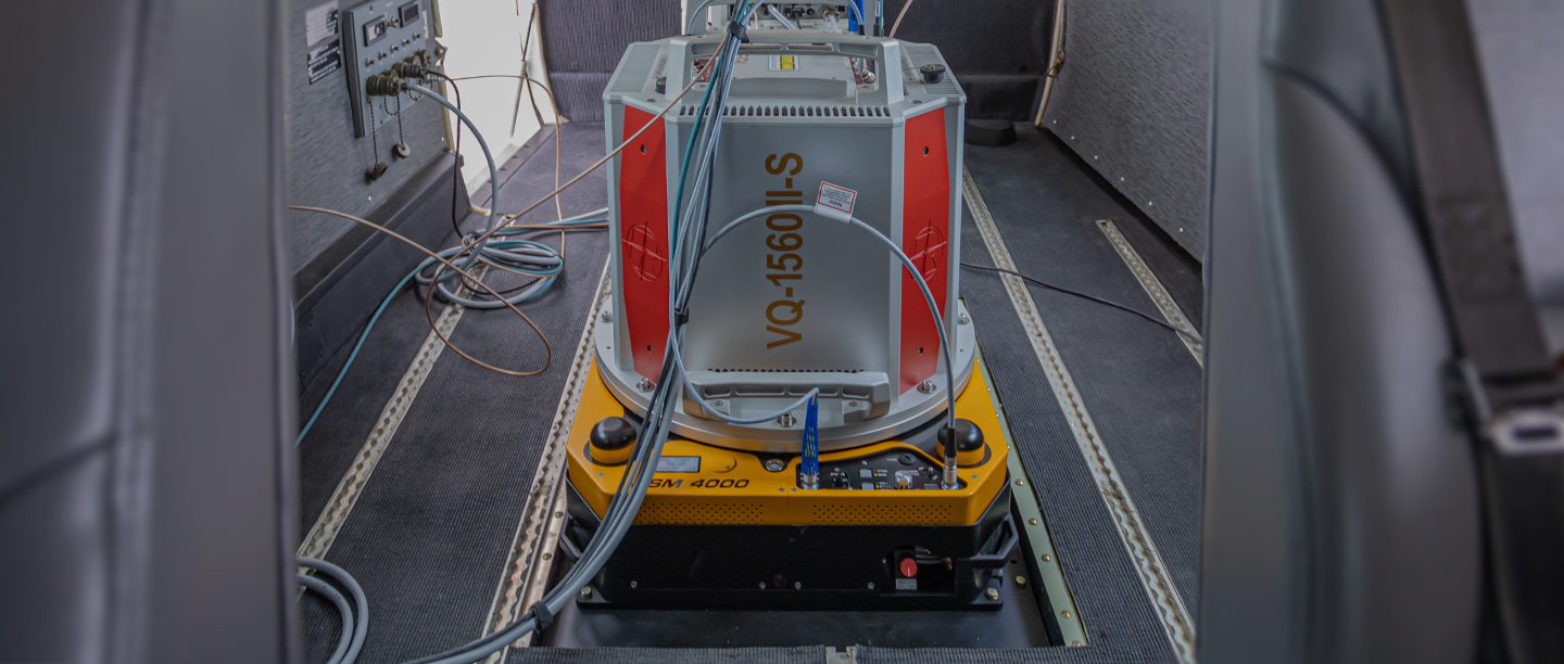
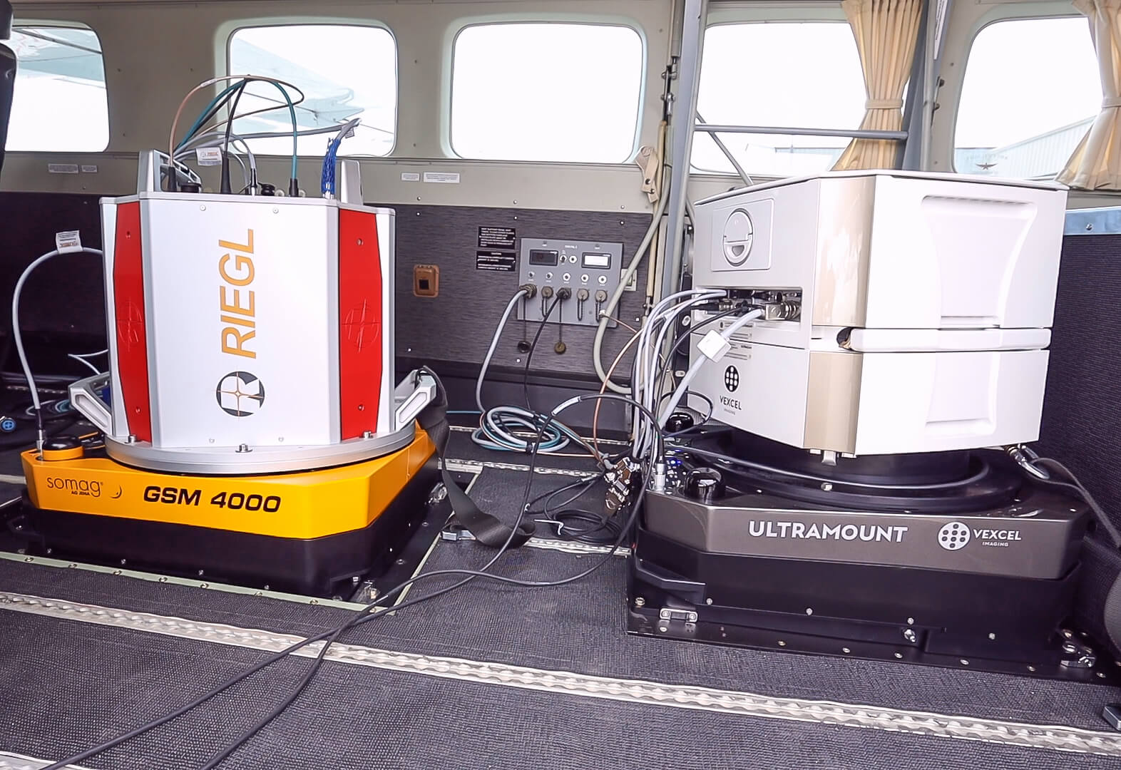
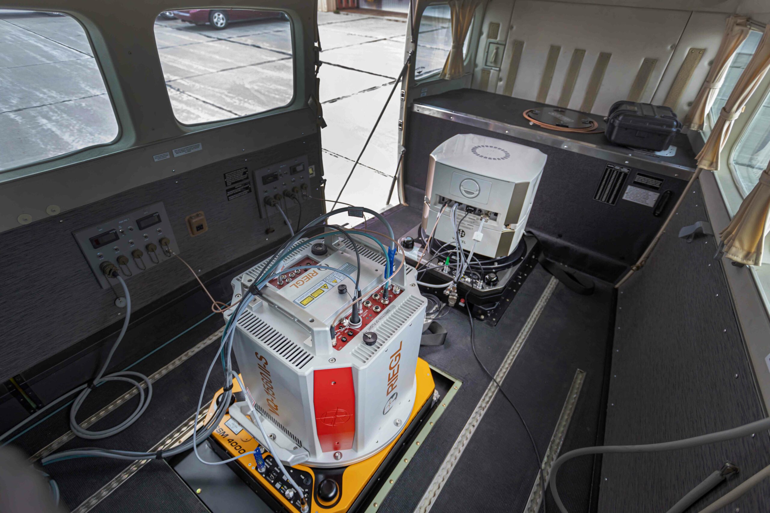
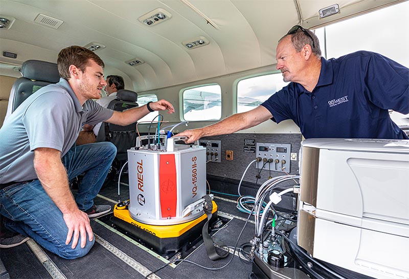
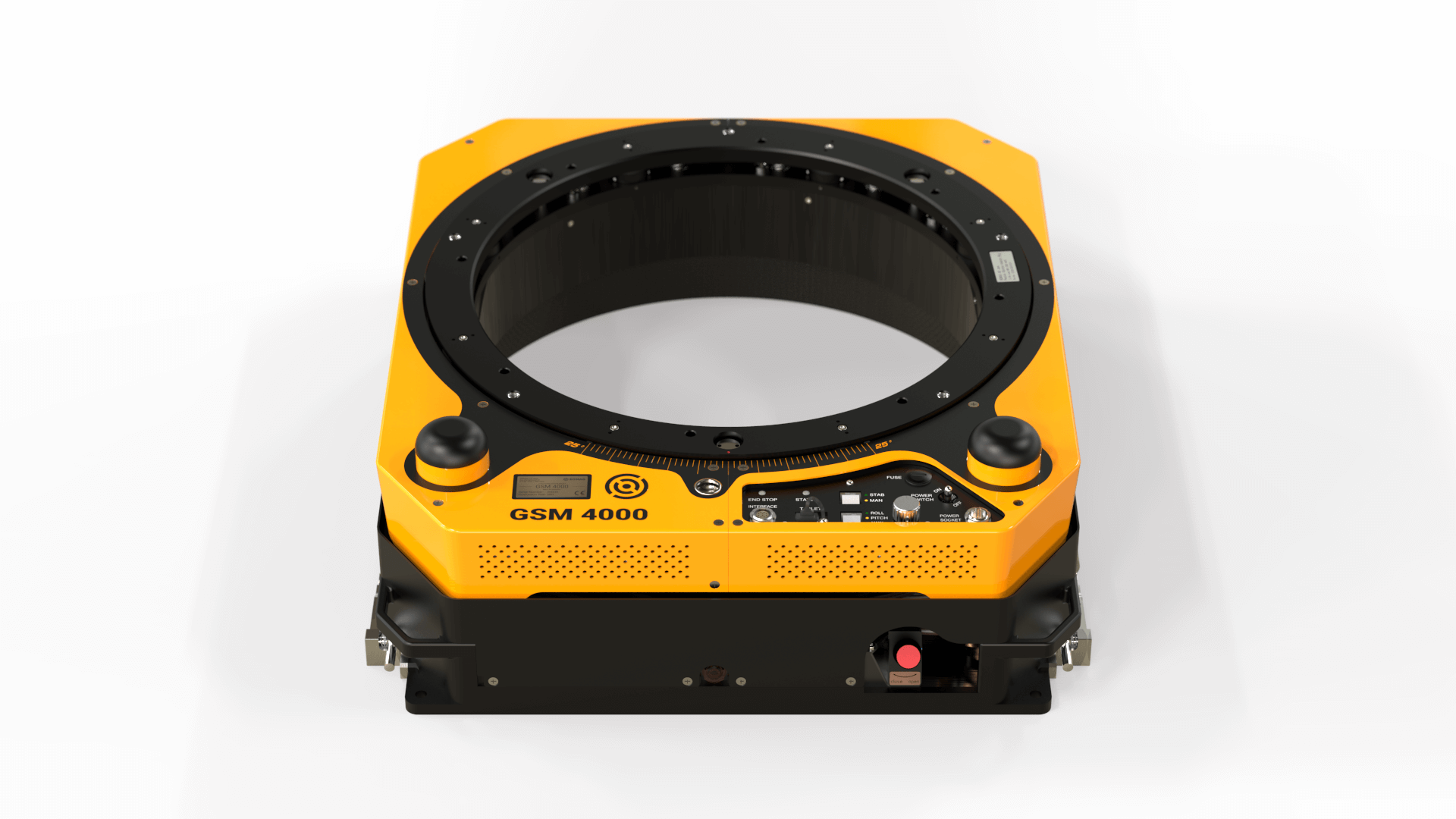
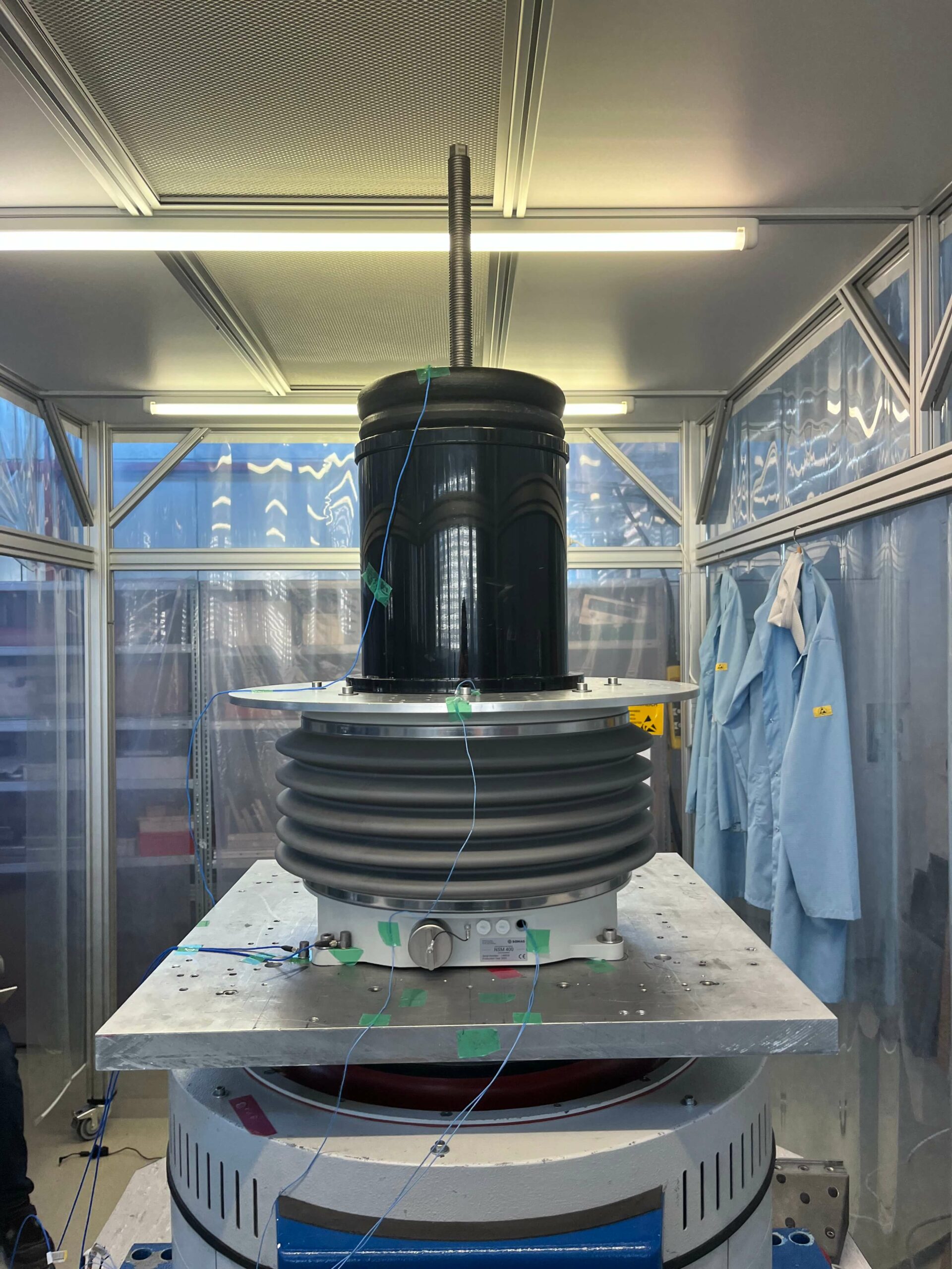
Tests were carried out on the NSM 400 with its maximum payload of 100 kg (220.5 lbs) with a center of gravity of 250 mm above the mounts pivot point. The test aims to verify the mechanical strength of the Mount and to observe its dynamic behavior. Testing was carried out in accordance with IACS E10 No. 7 Vibration and DIN EN 60068-2-06.2008-10.

First, a sinusoidal sweep test was performed with a frequency range from 2 to 300 Hz. From 2 to 13 Hz the excitation amplitude equaled 1 mm, afterwards it depended on the acceleration of the shaker with 0,7g. The resonance test was run in all three space axes (x, y and z) and aimed to find the resonance frequencies of the Mount.

A total of 5 accelerometers (4 x single axis accelerometers and 1 x single accelerometer for control) were placed at the base plate, the top part and at the supporting structure of the stabilization platform to measure the resulting vibrations. In addition, a three-axis acceleration sensor was attached to the payload in order to measure the resulting vibrations there as well and thus incorporate the real use of the Gyro Mount with payload in the test.

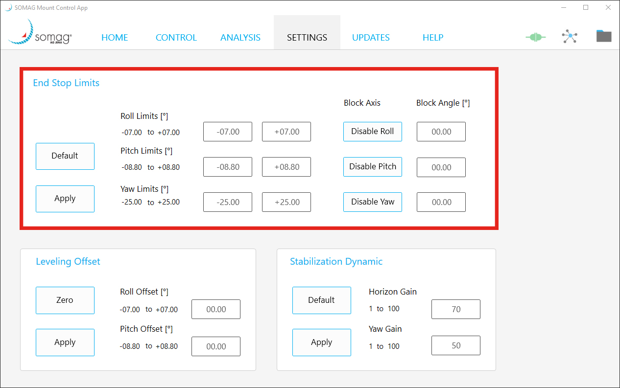
“To meet the standard, it would have been sufficient to test the unit in non-operational mode. However, we wanted to go one step further and also test the mechanical-dynamic behavior of the mount in MAN and STAB mode. In all three scenarios the NSM performed just as desired,” explains Sebastian Schreiber, CTO at SOMAG.

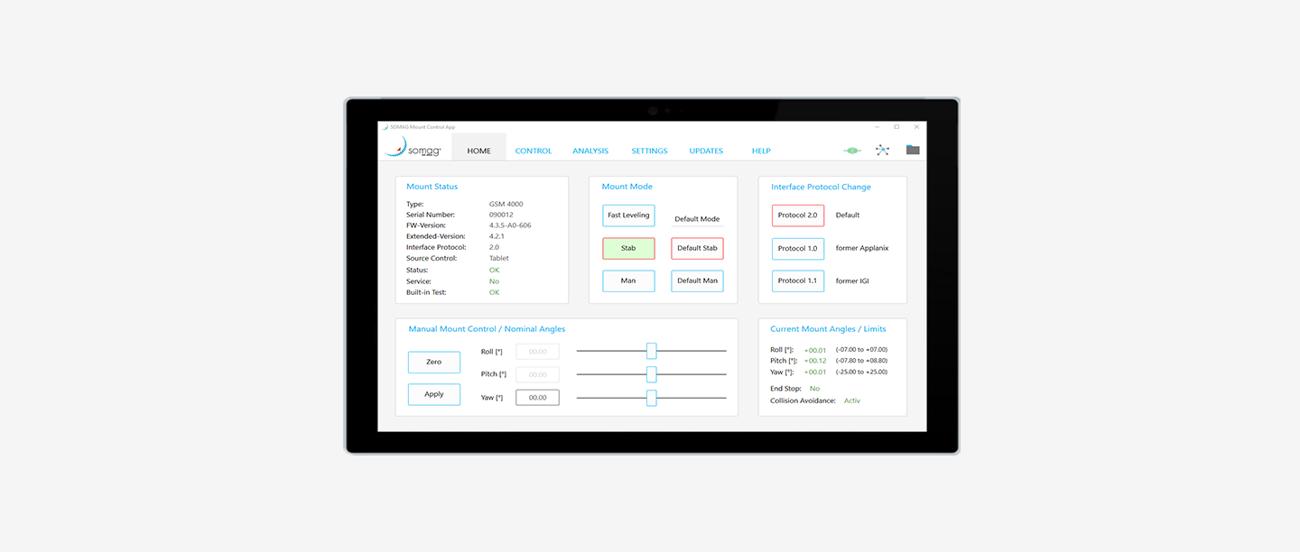
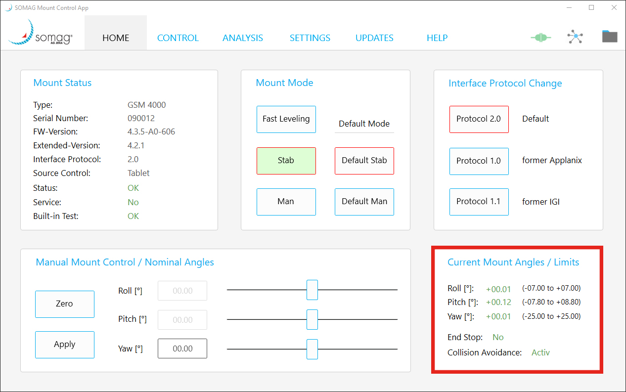
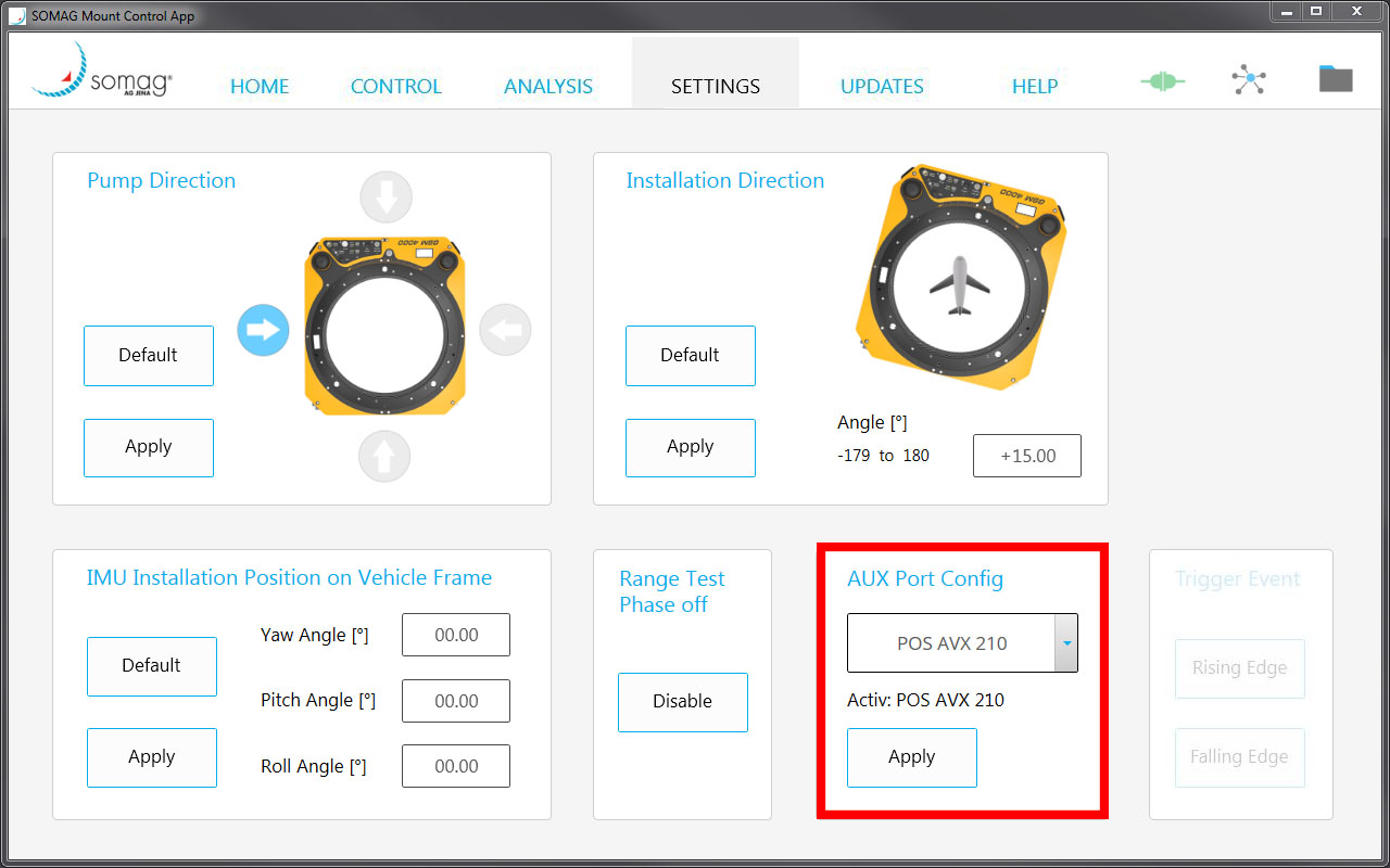
After the resonance search the visual check was passed. There was no external damage and no visual deficiency after the test. The self-test via the SOMAG Mount Control App could also be performed successfully which was the success criteria for the test.

Since resonances with an amplification factor ≥ 2 were found in the sinusoidal sweep test, additional endurance tests (1.5 h each) were performed at each of these frequencies. The visual inspections after the endurance test did not reveal any damage or optical defects. The self-test via the Mount Control App could be performed successfully in all cases and the vibration tests were completed successfully overall.

Newsletter

Subscribe today!

Keep yourself informed about SOMAG and the latest Gyro Mount technology.
We will send you regular information about:

  • exhibitions and event invitations
  • new products, services and videos
  • latest application examples, projects and partnerships

Subscribe here

Subscribe to the SOMAG newsletter
Customer Success Story

Simultaneous Lidar Data and Aerial Imagery Collection with GSM 4000

95West Aerial Mapping revolutionizes simultaneous large-format imagery and high-density lidar collection with a dual GSM 4000 gimbal setup. The US-based company has been performing simultaneous collections for many years. When they decided to upgrade their current equipment, they opted for two SOMAG GSM 4000s as their preferred Gyro Stabilization Mounts for their state-of-the-art sensors. Simultaneous data collection allows the company to serve customers with maximum quality and efficiency.

The Gyro Stabilization Mount 4000 provides industry leading pitch, roll, and yaw stabilization for airborne cameras, scanners, LiDARs and other imaging sensors up to 120 kg during flight missions. Since September 2021, 95West has been operating the dual GSM 4000 Mounts in a Cessna Caravan to stabilize a Vexcel UltraCam Eagle M3 and a Riegl VQ-1560 II-S scanner. The Gyro Mount ensures high quality aerial images taken with the large format camera and a regular distribution of measurement points on the ground for the Lidar scanner, as well as a significant increase in efficiency when flying over large areas by reducing the required overlap of neighboring scan strips.

Two SOMAG GSM 400 Gyro Mounts - left in SOMAG signature yellow, right in UltraMount design stabilizing a Riegl lidar scanner and an UltraCam aerial camera
Two GSM 400 Gyro Mounts – left in SOMAG signature yellow, right in UltraMount design
GSM 4000

Advantages for Lidar and Imagery Products

  • High data quality

    enables customers to provide their clients with the highest quality lidar and imagery products
  • Precise motion compensation

    compensation of high winds or turbulence and prevention of excessive crab angles and image blur
  • Productivity

    allows to maximize flight opportunities while minimizing reflights
Why Customers

Trust Somag

„We chose to go with dual SOMAG mounts for our sensors because of the reputation for high performance stabilization, ease of use, and flexibility of integration. Having one mount that is compatible with both sensors, communicates flawlessly with the Applanix IMU and our TopoFlight FMS made integration very smooth. It also gives us flexibility to rearrange systems without having to refabricate aircraft adapter plates. When planning our equipment upgrade there were no alternatives, the SOMAG GSM4000 was a must for both our Riegl VQ-1560 II-S and UltraCam Eagle.”

Andrew Werle, Pilot at 95West Aerial Mapping
Maximum efficiency at minimum costs

Advantages Simultaneous Data Acquisition

Top view on two SOMAG gimbals with a Riegl lidar scanner and a Vexcel Imaging aerial camera system

With small time windows for data acquisition due to weather, sun angle limitations, and seasonal changes, the number of flight hours per season is limited. By acquiring lidar and imagery data in the same flight, weather windows are maximized and mobilization and acquisition costs are halved.

All advantages at a glance:

  • Coincident datasets reflect same features and water levels eliminating discrepancies
  • Single mobilization expense
  • More efficient acquisition 
  • Maximum utilization of weather windows
  • Larger image footprints and swath widths 
  • Increased detail and precision 
  • Data versatility 
  • Current terrain data for orthorectification 

“We find that many of our clients prefer simultaneous collection. Even customers who would not normally use both lidar and imagery have chosen to acquire both systems because of the greater versatility and benefits.”
– Andrew Werle, 95West Aerial Mapping

Customers from diverse sectors benefit from the dual solution. Engineering and utility customers use the highly accurate terrain models for design while using the high-resolution imagery as a background raster for their drawings. Customers in the mining and commodities industries are able to monitor properties and calculate volumes in a single flight. For orthophotography customers, a much better product can be delivered because the most current surface data can be used for rectification.


95West operating the dual GSM 4000 Gyro gimbals in a Cessna Caravan
GSM 4000

Self test

The video shows the self test of the GSM 4000. It consists of a mechanical and an electronic test phase. The self test executes a routine, which checks all sensors, mechanics and electronics and saves the results in a text file. SOMAG can decrypt this text file and utilize it for trouble-shooting purposes. The test can be performed in the SOMAG Mount Control App. which is delivered together with each Gyro Mount on a USB stick.

About SOMAG AG Jena:

SOMAG AG Jena is a global specialist for high-precision gimbal systems. The company, consisting of hand-picked experts in the fields of electronics, mechanics and software, focuses since 2004 on the development and manufacture of Gyro Stabilization Mounts for data acquisition and surveillance applications in the air, on land and at sea.

About 95West Aerial Mapping:

95West Aerial Mapping is a wholly owned subsidiary of Widseth that provides aerial acquisition and geospatial services throughout the United States and Canada. 95West specializes in unique solutions utilizing cutting edge equipment to deliver services that are tailored to their clients’ needs with the latest technology in the aerial industry.

Newsletter

Subscribe today!

Keep yourself informed about SOMAG and the latest Gyro Mount technology.
We will send you regular information about:

  • exhibitions and event invitations
  • new products, services and videos
  • latest application examples, projects and partnerships

Subscribe here

Subscribe to the SOMAG newsletter
SOMAG AG Jena

to launch revised Software Features

On the occasion of this year’s Intergeo, SOMAG AG Jena presents its newly revised software features. SOMAG AG Jena offers a number of software features that help customers to adapt their Gyro Stabilization Mounts to their individual needs and requirements. These features have been intensively evaluated and adapted over the past months and will be available from the beginning of October.

CTO Sebastian Schreiber comments: “We have completely revised our software features to align them even more closely with customer needs. They include new functionalities and have been bundled into attractive packages.”

For GSM 4000 customers, SOMAG launches a new feature called Collision Avoidance.

Collision Avoidance

Which application issue is solved?

If the Mount and the sensor have to be installed close to the board wall inside the aircraft or if the hatch in the fuselage is narrow, the sensor system may collide with an obstacle. This may happen during the initialization phase of the Mount or while it is using its full angular range during stabilization. In the past, customers needed several individual software features (End Stop Limits, RTP off and Pump Direction) to avoid collision.

What’s new?

This problem is now solved with only one combined feature – Collision Avoidance. It includes the following functions:

  • The End Stop Limits settings allows customers to limit the physical movement range of the Mount in all three space axes. If the End Stop Limits have been applied, the Mount will only move within the specified angle ranges.
  • The End Stop Limits and the Block Axis function are now linked together. The block axis function allows users to block the movement of one or multiple axes. For example, if the hatch hardly offers enough space for the Mount to stabilize in all three space axes and therefore preventing horizontal movement compensation, Block Axis can be used to disable these two axes. This enables the Mount to at least compensate the drift motions.
  • It is now also possible to block an axis at a certain angle.
  • Furthermore, an axis blocking now takes place automatically if the absolute difference of the entered end stop values is <± 2°.
  • Limited installation space in the aircraft may result in the sensor system hitting an obstacle such as a board wall during the initialization phase when the Mount is pumping up. The function Pump Direction allows customers to select the side on which the GSM 4000 pumps to working height during the initialization phase. Without feature activation, the Mount pumps up via roll positive by default.
  • The Pump Direction function is now linked to the End Stop Limits. This means, if a change of the Pump Direction is necessary due to the restriction of roll and pitch, a possible Pump Direction will be set automatically.

Adjustment of the Mount’s working height

  • A novelty of the Collision Avoidance feature is the adjustment of the Mount’s working height. The Mount now automatically adjusts its working height when all four values in roll and pitch have been reduced. In this way, the Mount and the sensor system are protected against a collision with an obstacle also in a non-powered state. The Collision Avoidance feature thus offers the greatest possible safety to avoid damage to the sensor due to restricted installation conditions.

    “We have also addressed customer feedback on the Range Test Phase, as well as the time of the entire initialization phase. We basically nailed it down to the minimum the Mount needs. The complete initialization phase takes now only 15 seconds which shortens the time until the Mount is fully functional tremendously”, Schreiber explains.

End Stop Limits including Block Axis

End Stop Limits including the option of axis blocking is still available as a single software feature for all Gyro Mounts. This software feature is particularly interesting for customers who need the movement range limitation for use cases other than collision avoidance. For example, if the hatch is too small and the sensor is located too close to the fuselage of the aircraft, this can lead to vignetting problems and thus to dark image corners. To solve this problem, it can be helpful to limit the sensor’s range of movement by activating the End Stop Limits feature.

How do I get the Software Features?

The Software Features can be ordered along with a new Mount. When customers receive the device, the Features are already activated and ready to be used.

If you already own one or more Mounts, you can order each Software Feature separately later at any time. In the meantime, the Mount remains fully operational as it does not need to be sent in. Once the feature was ordered, SOMAG provides an activation file on the same day without long lead times.

Where can I adjust the Software Feature settings?

To activate and use the Features you only need the SOMAG Mount Control App. SOMAG provides this in-house developed app for every Gyro Stabilization Mount free of charge. The app allows you to manually control your Mount, to update the firmware and it provides access to documents like Mount manuals.

Customers will also find an overview of all optional Features. These are greyed out at the beginning. After activating the respective feature, it will be colored and can be controlled.

Is the use of the Software Features limited in time?

There is no expiration of a license period and no need for reactivation. Once purchased, the feature can be used at any time. Each software feature activation is directly linked to the serial number of a Mount and can only be used with the respective Mount. If the same feature is to be used on multiple Gyro Mounts, the feature must be ordered separately for each device. If you are interested in more than one Feature, we are happy to offer special conditions for software packages.

For questions and pricing information please contact SOMAG Sales Manager Mr. Sören Lieske at s.lieske@somag-ag.de


Newsletter

Sign up today!

Keep yourself informed about SOMAG and the latest Gyro Mount technology.
We will send you regular information about:

  • exhibitions and event invitations
  • new products, services and videos
  • latest application examples, projects and partnerships

Subscribe here

Subscribe to the SOMAG newsletter
New GSM 4000 feature

Aux Port interface now available for the GSM 4000

We would like to draw your attention to a technical innovation for one of our devices. The Aux Port interface is now also available for our GSM 4000. All our airborne as well as all marine and land Mounts offer this feature now.

To use the Aux Port the optional software feature “Aux Port” is required. This feature can be ordered directly with a new GSM 4000 or it can be activated after the purchase of the unit. With every delivered Mount we provide the SOMAG Mount Control App. Under the tab Settings (Settings 2) you will find the Aux Port Config panel, necessary settings can be adjusted there. The used IMU can be selected in the combo box and activated via the Apply button.

You have an older Mount and want to upgrade the interface? No problem! Get in touch and we will find a solution together.

The Aux Port offers various advantages:

  •  You have the possibility to connect two devices with your Mount, by using a y-cable. You can link an IMU and a Flight Management System (FMS) at the same time. This can be useful if your current FMS does not pass the IMU data directly to the Mount or if the Mount gimbal data need to be stored in real-time within the IMU.
  • If you do not have an FMS or 3rd party navigation system, you can connect your IMU directly to the Mount via the Aux Port interface. The IMU data improves the stabilization performance of the Mount in terms of leveling and especially heading.
  • An additional advantage of the IMU data coming via the AUX port is that the Mount automatically detects when a curve is entered during flight and switches the drift compensation into “freeze” mode until the curve is finished. This avoids the need to manually switch off the drift before flying a curve and switch it on again manually afterwards.

The following IMUs are currently supported:

  • Applanix POS AVX 210
  • SBG Ellipse, Ekinox and Apogee Series / Model E, N, D, U
  • Novatel OEM719, OEM729, OEM7500, OEM7600, OEM7700, OEM7720, PwrPak7, SPAN CPT7, SMART7-S
  • Advanced Navigation Spatial FOG

The communication between the IMU and the Mount is based on a defined port setting and determined commands which are listed in the SOMAG Mount Control App manual. If you want to use an IMU that is not listed here, just contact us. The integration of further IMUs is possible at any time.

Newsletter

Subscribe today!

Keep yourself informed about SOMAG and the latest Gyro Mount technology.
We will send you regular information about:

  • exhibitions and event invitations
  • new products, services and videos
  • latest application examples, projects and partnerships

Subscribe here

Subscribe to the SOMAG newsletter