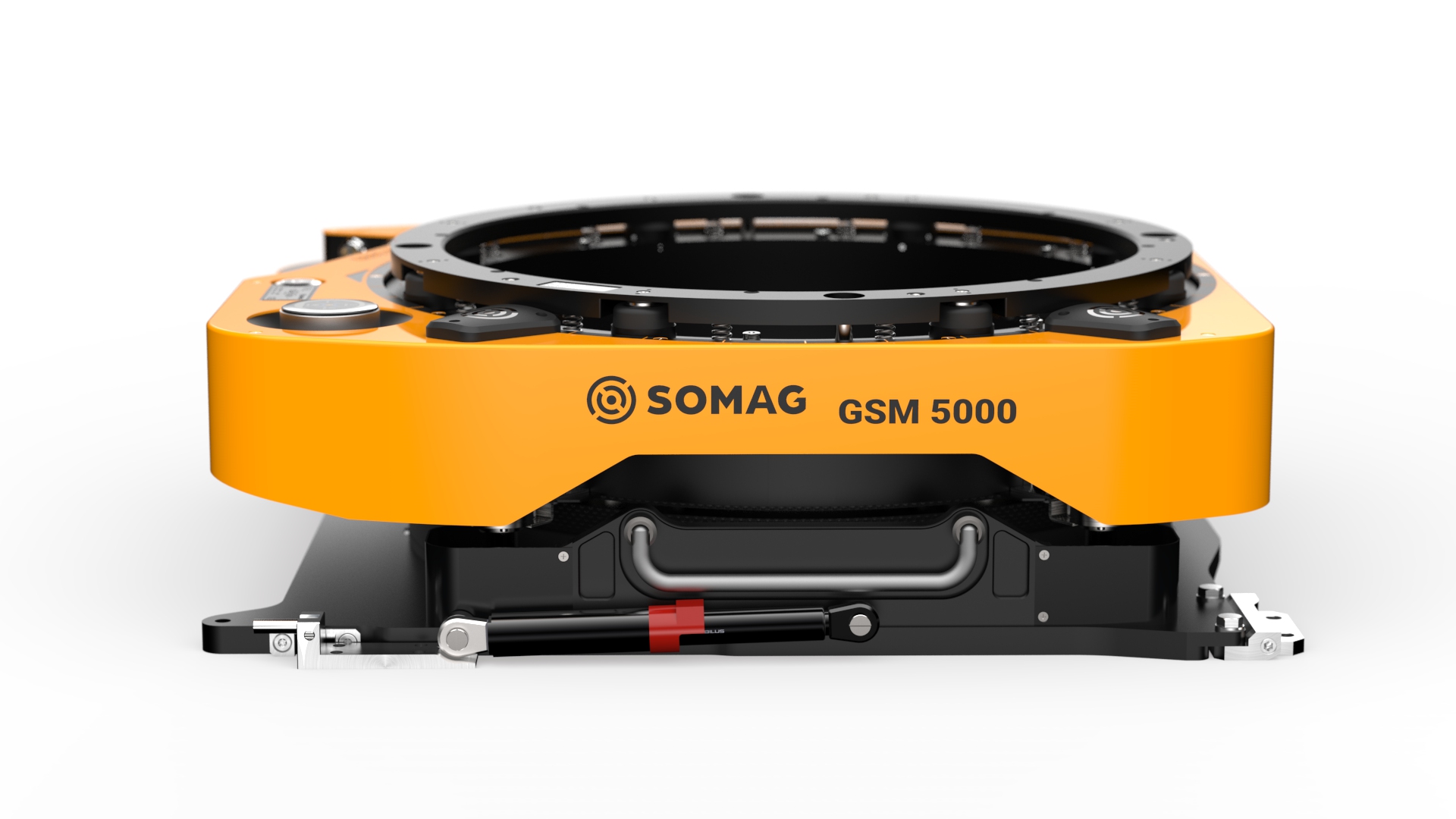
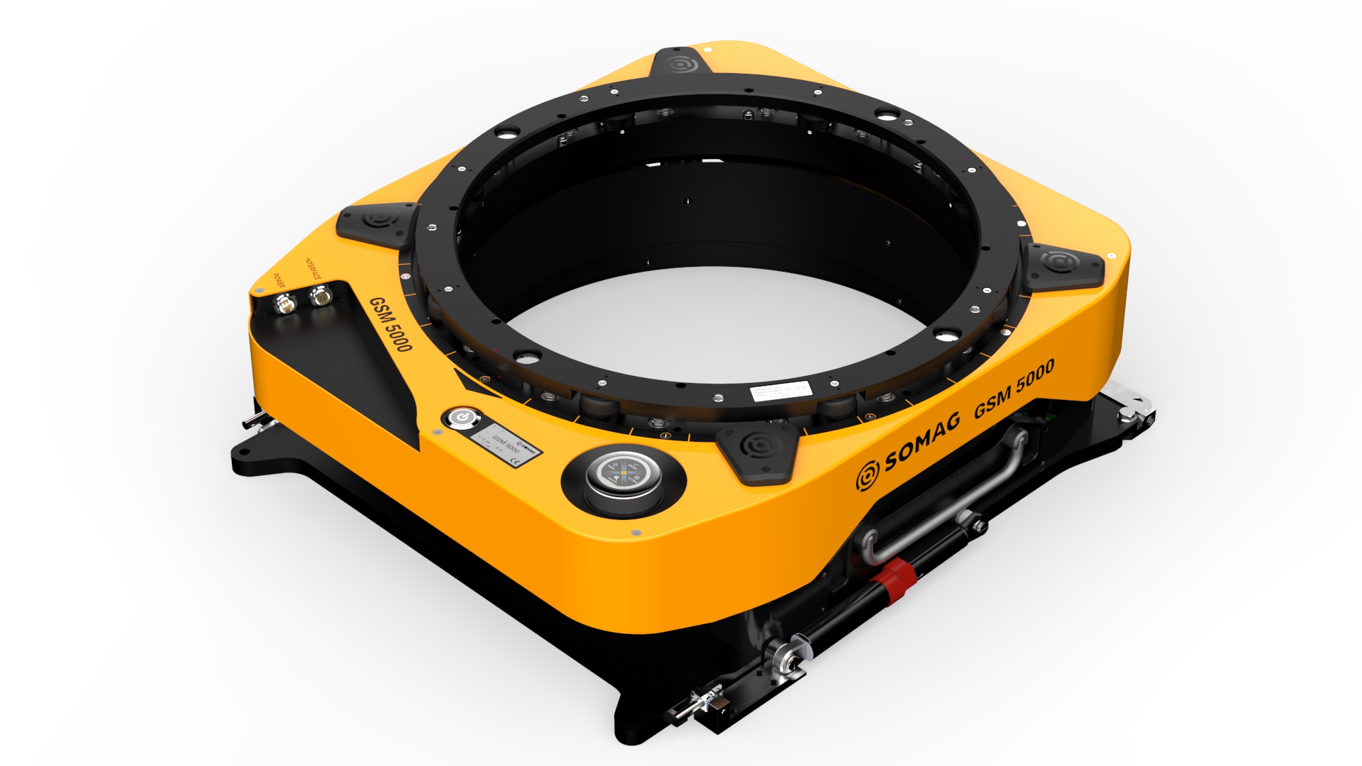
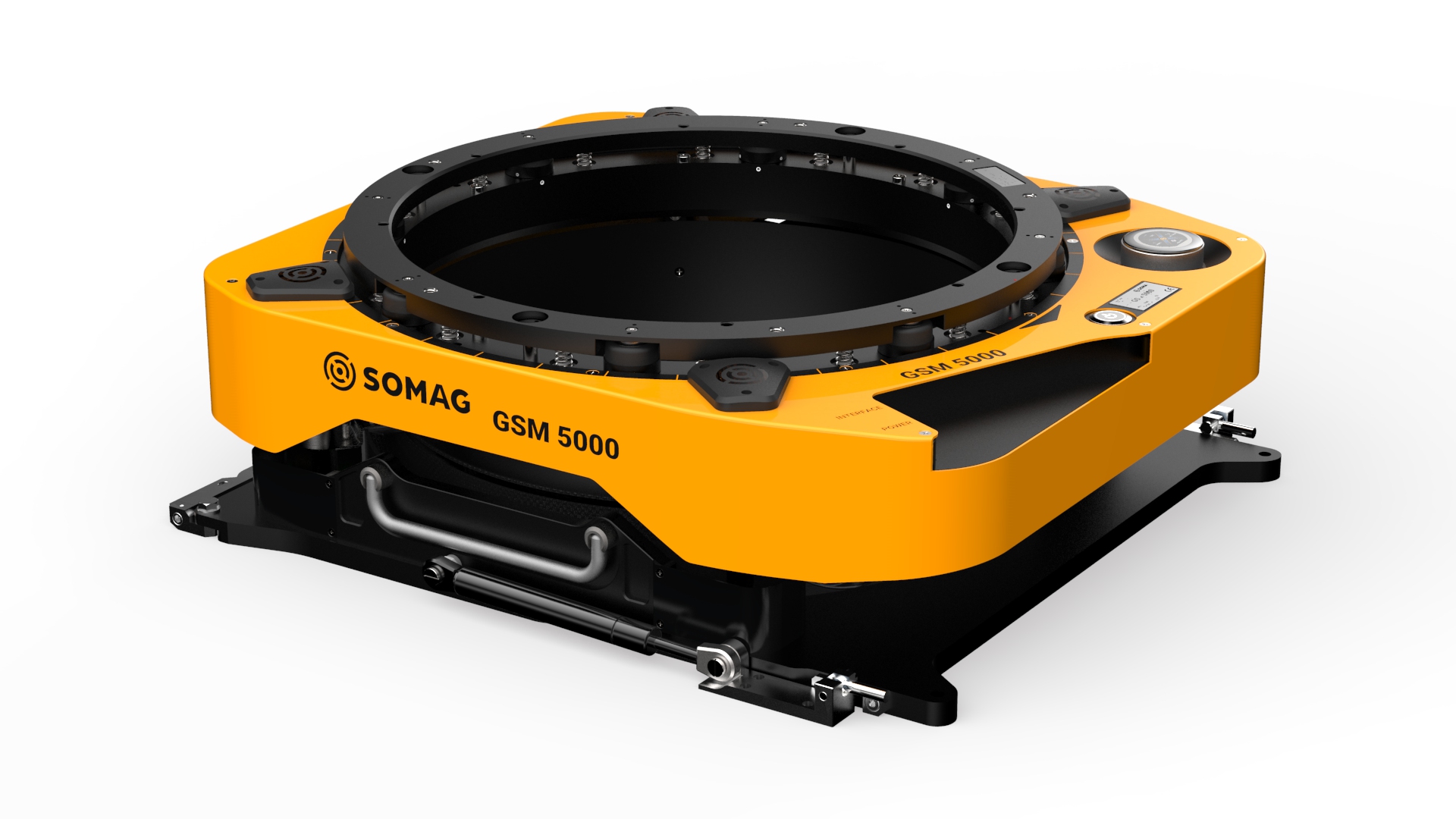
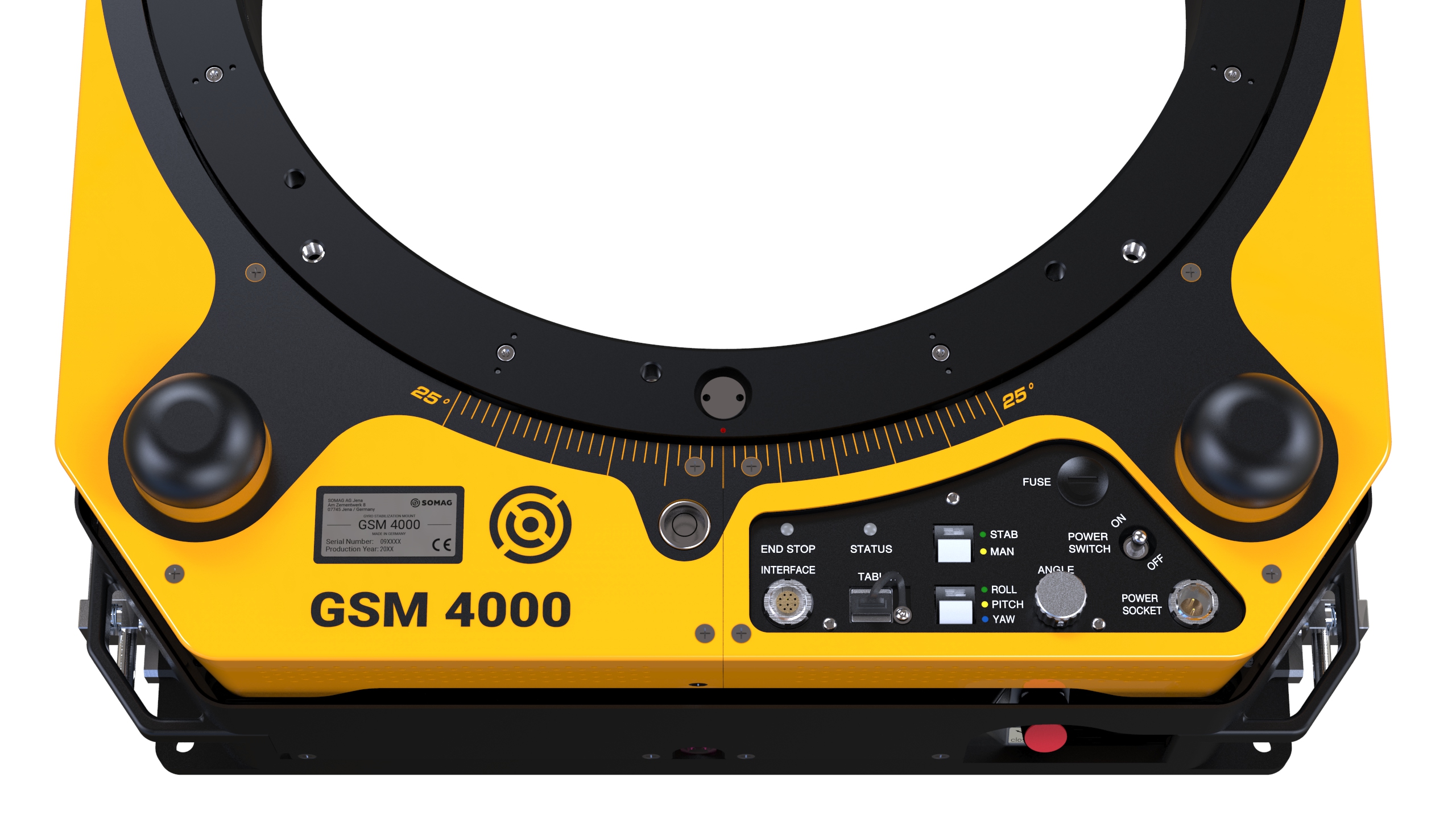
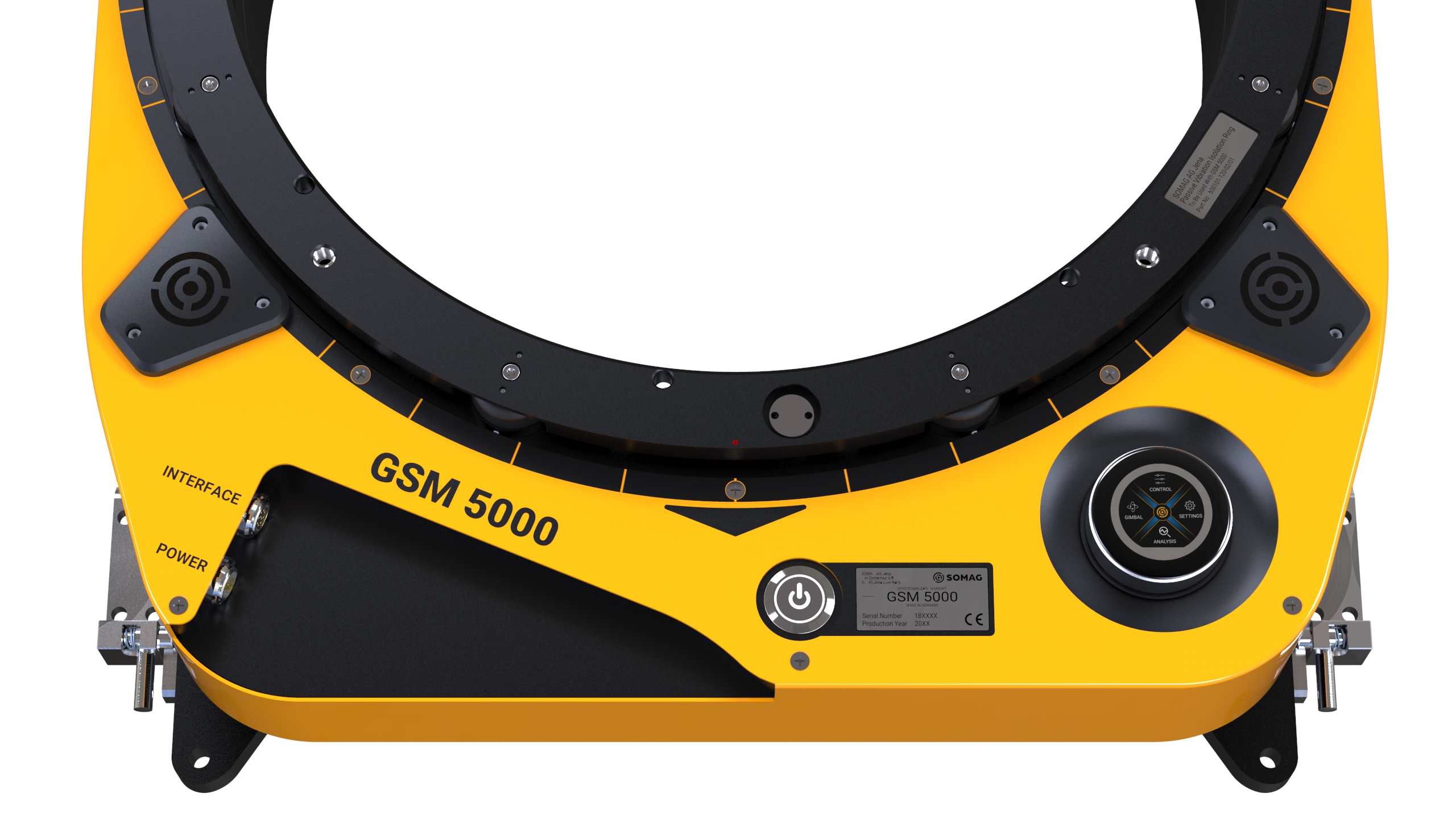
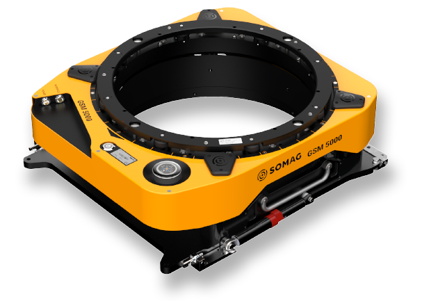
The Gyro Stabilization Mount GSM 5000 is the successor of the world renowned GSM 4000 and the flagship of SOMAG AG Jena’s airborne gyro mount line.
Advantages
- Industry standard for large format cameras and scanners
- Highest payload stabilization of SOMAG Airborne Gyro Stabilization Mounts
- Highest stabilization accuracy of SOMAG Airborne Gyro Stabilization Mounts
Key Enhancements and Features
Expanded Motion Range in Roll, Pitch, and Yaw
Compared to its predecessor, the GSM 4000, the GSM 5000 offers an increased range of motion, with pitch capability improved from ±8.8° to ±10.1°, roll capability from ±7° to ±8.1°, and drift capability expanded from ±25° to ±30°. This translates to a 33 % increase in the range of motion for roll and pitch, and a 20 % and 610 % increase for drift, respectively, when considering a range of ±177.5°. These enhancements ensure superior stabilization and accuracy, providing a significant upgrade over the GSM 4000.
355° Absolute Drift Movement
The GSM 5000 features a near-complete rotational range in the drift axis, offering a 355° absolute movement capability, which is crucial for comprehensive data collection during flights. This extended movement range will be available through the Software Feature ‘Extended Drift Movement Range’ and will provide, in addition to standard drift stabilization, three additional modes:
- Step and Stare Mode
- Scan Mode
- Pointing Mode
Increased Usable Diameter
The internal diameter has been expanded from Ø410 mm to Ø425 mm, enabling the integration of larger and more complex sensor systems, potentially including multiple sensors for enhanced data capture.
Internal Logging
The GSM 5000 offers enhanced data management with the new internal logging feature, allowing for easy recording and transfer of operational data, increasing the system’s flexibility and utility. Additionally, comprehensive internal logging, including error logging, supports rapid identification and diagnosis of issues, reducing downtime and improving operational safety. By monitoring trends and patterns in operational data, potential problems can be detected and resolved early, preventing failures. Furthermore, the analysis of collected data, particularly motion data, allows for fine-tuning of the platform to maximize stabilization efficiency and further optimize performance.
Enhanced Communication Interfaces
The GSM 5000 supports advanced communication with RS232, and Ethernet interfaces, offering significant improvements over the GSM 4000. In the GSM 4000, each application required its own dedicated interface: USB for the Mount Control App, RS232-MAIN for the Mount Communication Protocol, and RS232-AUX for the AUX Port Interface. The GSM 5000, however, simplifies this by retaining RS232-MAIN for compatibility purposes while introducing two flexible universal interfaces: Ethernet and RS232-COMBI. These universal interfaces are designed to handle all applications (Mount Control App, Mount Communication Protocol, and AUX Port) through a single connection, providing significant added value. The COMBI interface, as the name suggests, can manage all three applications simultaneously.
In addition, the Ethernet interface brings further improvements:
- It supports long cable distances, allowing for greater spatial flexibility.
- It offers much faster data transmission speeds compared to RS232 interfaces.
- Ethernet is network-capable, enabling multiple mounts to be connected and accessed simultaneously, whereas RS232 only allows a single mount to be connected to the PC at a time.
Optimized Pivot Point for FOV Advantage
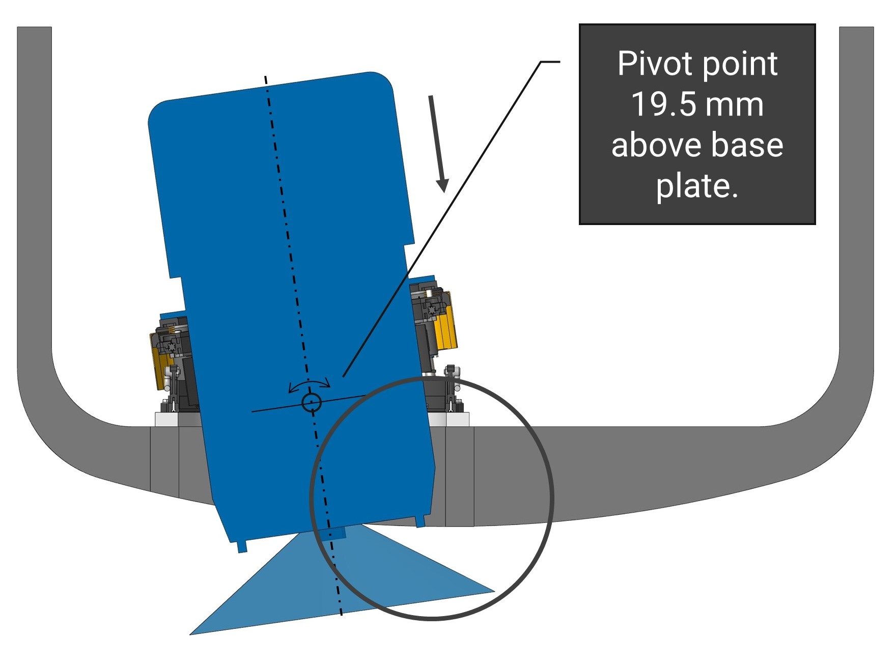
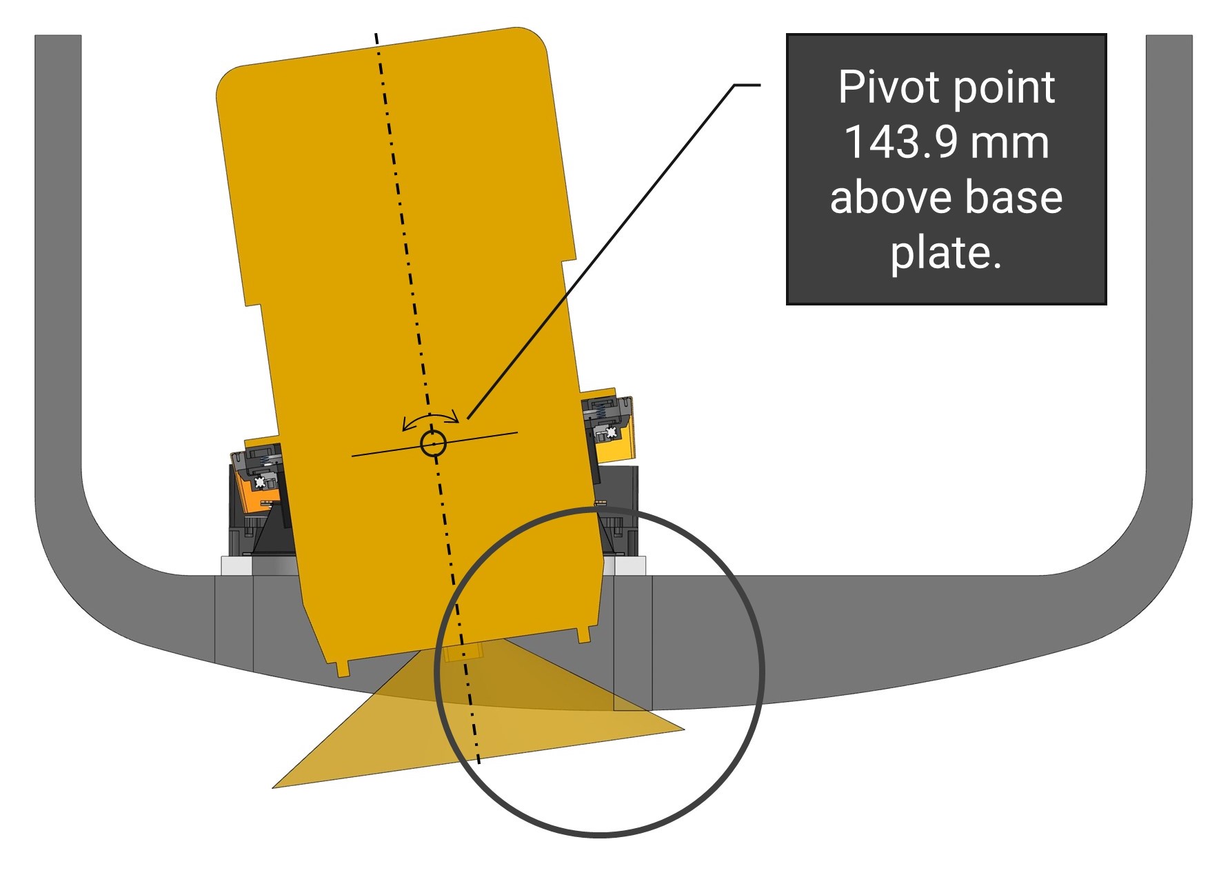
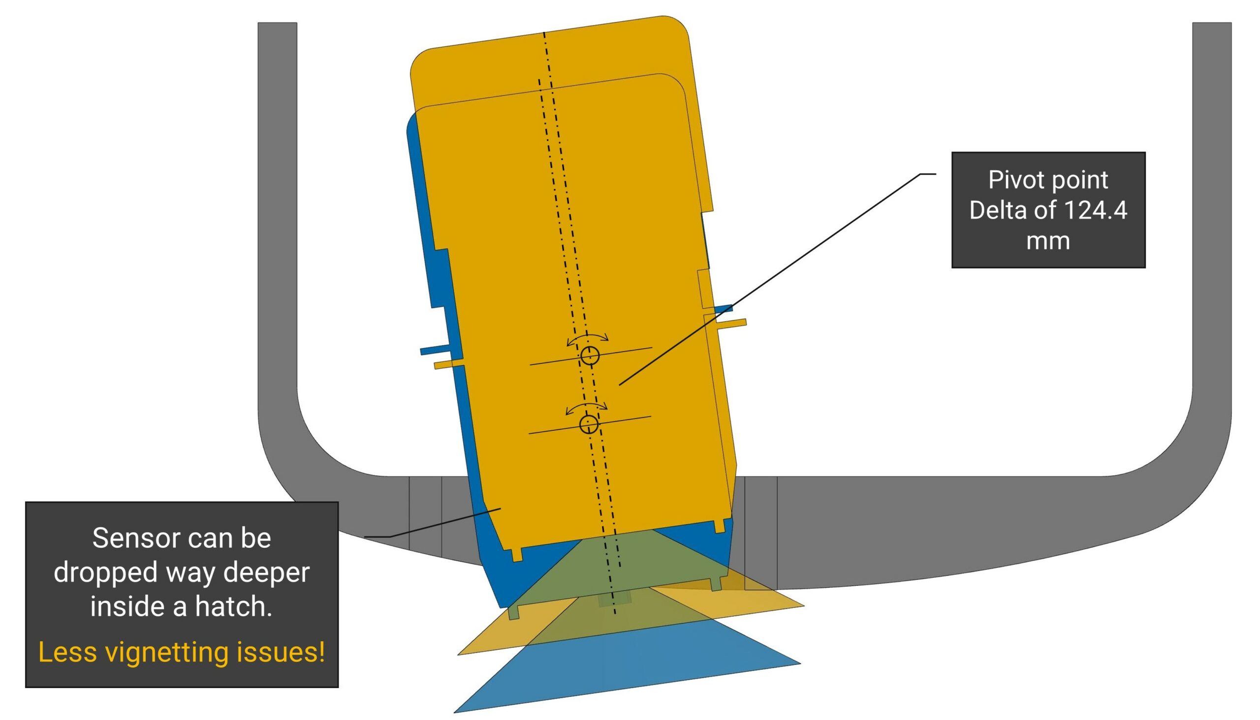
The pivot point of the mount has been strategically relocated to the base plate, minimizing sensor system displacement in the aircraft hatch during horizontal rotation and reducing the risk of collisions. This design innovation enhances the field of view (FOV) for the sensor system and can eliminate movement restrictions, provided the sensor systems allow for deeper installation within the hatch and mount.
The following graphic illustrates the relocation of the pivot point. The GSM 5000 is marked in blue and the GSM 4000 in yellow.
Hydraulic Innovations
The GSM 5000 no longer requires a manual valve that the operator must use to hydraulically lower the mount to the lowest position. Instead, the GSM 5000 is lowered via software using the touch encoder on the GSM 5000 or the Mount Control App. If the working height of the mount is too high, the valve can autonomously release oil to restore the correct working height.
Additionally, the system is equipped with a hydraulic oil level sensor in the tank. This sensor automatically checks if there is sufficient oil to perform a pumping process, removing the need for the operator to handle this check manually.
User-Friendly Interface
GSM 5000
- Simplified, user-friendly interface
- Digital user interface with touch encoder
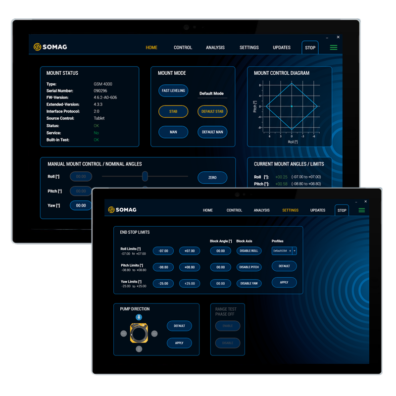
- New interface provides enhanced control options, including manual gimbal adjustment, mount lowering via the electric valve, a digital inclination display, and quick access to status and error messages
- No movement restrictions for the sensor system due to horizontal cable routing and removal of ‘high points’ such as motor cover caps
- All elements positioned below the mounting plane, eliminating collision risks
Backward Compatibility
The GSM 5000 maintains compatibility with the power and interface cables of the GSM 4000, making it easy to upgrade existing installations. The mechanical mounting holes on the base plate and in the bearing are identical to those on the GSM 4000, allowing for seamless replacements. The mounting holes are also more accessible than those on the GSM 4000, simplifying installation and maintenance.
Specifications
| Angular Stabilization Ranges | Pitch at 0° Roll: Roll at 0° Pitch: Yaw (Drift): | -10.1° … +10.1° -8.1° … +8.1° -30.0° … +30.0° | -177.5° … +177.5° (optional1) |
| Residual Angular Rate2 | ≤ 0.2°/s rms | |
| Residual Deviation | without IMU Support2: with IMU Support2,3: | ≤ 0.3° rms ≤ 0.02° rms |
| Payload4 | 10…120 kg | 22…265 lbs | |
| Mass | 28.5 kg | 63 lbs | |
| Dimensions (Regular Leveling Positions) | Length: Width: Height5: | 600 mm | 23.6 in 530 mm | 20.9 in 198 mm | 7.8 in |
| Usable Diameter | Ø425 mm | Ø16.7 in | |
| Operating Temperature | -15 °C …+55 °C | 5 °F…+131 °F | |
| Storage Temperature | -55 °C…+85 °C | -67 °F…+185 °F | |
| Communication Interfaces | Ethernet | RS 232 | |
| Internal Logging Capacity | 32 GB | |
| Operational Voltage | 28 VDC (24…30 VDC) | |
| Average Power Consumption at Operational Voltage | 50 W | |
| Peak Power Consumption at Operational Voltage | 200 W | |
| Applied Standards | RTCA DO-160-G, EUROCAE-14G, ISO 7137, 2006/42/EC Machinery |
| Preliminary data, subject to change without notice. The technical specifications in the metric system represent the binding reference values. The imperial units are rounded approximation and are provided for reference only. 1 Activation of the extended drift movement range is possible through an optional software feature 2 Vehicle angular motion <7.5°/s and with typical data acquisition profile frequency spectrum 3 Deviation from perpendicular depends on accuracy of used IMU 4 Minimum payload is based on usage of Passive Vibration Isolation Ring 5 Minimum 167.5 mm (6.6 in) / Maximum 228.5 mm (9.0 in) |
Applications
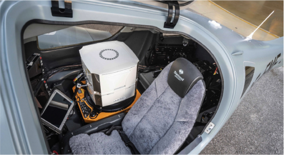
For precise airborne surveying and blur-free images taken from above, they have become indispensable and an established part of the overall equipment: Gyro Stabilization Mounts. Installed into the fuselage of aircraft, they compensate for its roll, pitch and yaw movements to keep the sensor in a leveled position. Would you like to see how SOMAG customers benefit from their Mounts? We have compiled a series of application examples for you that show the diversity of application scenarios for our devices.
Official Launch Presentation
Downloads
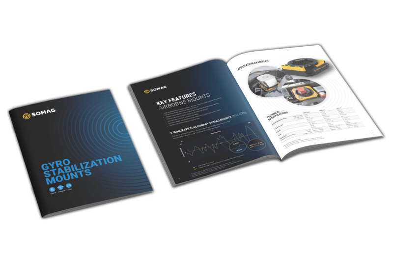
Discover all Gyro Stabilization Mounts with their specifications at a glance in our new product catalog. Below you will also find Mount-specific documentation. Do you need other documents? Then do not hesitate to contact us. We will gladly send you manuals on request.
Mount Control App and Software Features
Mount Control App
For all Gyro Stabilization Mounts, SOMAG provides a self-developed Mount Control App with numerous features. It is your all-in-one tool for managing your Mount. The app is part of the standard scope of delivery of each device and is delivered on a USB stick together with the Mount.
Software Features
SOMAG offers optional Software Features which allow you to customize your Mount individually to your mission requirements. Feature management and settings can conveniently be made in the SOMAG Mount Control App. Get the most out of your stabilization platform and learn more about the optional Software Features.
