You are using an aerial survey system including a SOMAG Gyro Mount but the installation conditions in the aircraft are challenging because the hatch is small? Are you want your Mount to point in a different direction than nadir? We have the solution to these questions. SOMAG AG Jena offers a number of Software Features that help you customize your Gyro Stabilization Mount to your individual needs and requirements. Please find below a summary of which optional Software Features are currently available for each Mount and a description of the individual Features. For more details on the Mount Control App and the settings of the optional Software Features, please consult the SOMAG Mount Control App Manual. It will be sent to you upon request. If you have a general question about our Software Fatures, then please have a look at our FAQ collection. If your question is not listed yet, feel free to let us know.
Software Features
| Software Feature | GSM 4000 | DSM 400 | CSM 40 | OSM 5000 (Marine/Land) | NSM 400 (Marine/Land) | RSM 50 (Marine/Land) |
|---|---|---|---|---|---|---|
| Collision Avoidance | x | |||||
| End Stop Limits incl. Block Axis | x | x | x | |||
| Leveling Offset | x | x | x | |||
| Status/Analysis | x (Standard Scope of Delivery) | x | x | x (Standard Scope of Delivery) | x (Standard Scope of Delivery) | x (Standard Scope of Delivery) |
| IMU Installation Position on Vehicle Frame | x | x | x | x | x | x |
| Installation Direction | x | x | x | |||
| Aux Port | x | x | x | x (Standard Scope of Delivery) | ||
Software Features
Collision Avoidance
Refers to: Refers to initialization phase and operating mode (stab/man) – GSM 4000 only
What is it?
The Feature combines the following functions to prevent a collision of the Mount and/or the sensor system with surrounding obstacles during Mount initialization or operation:
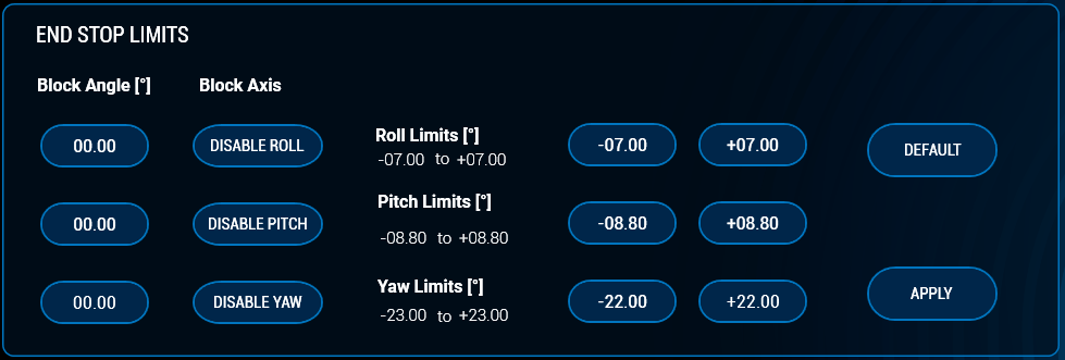
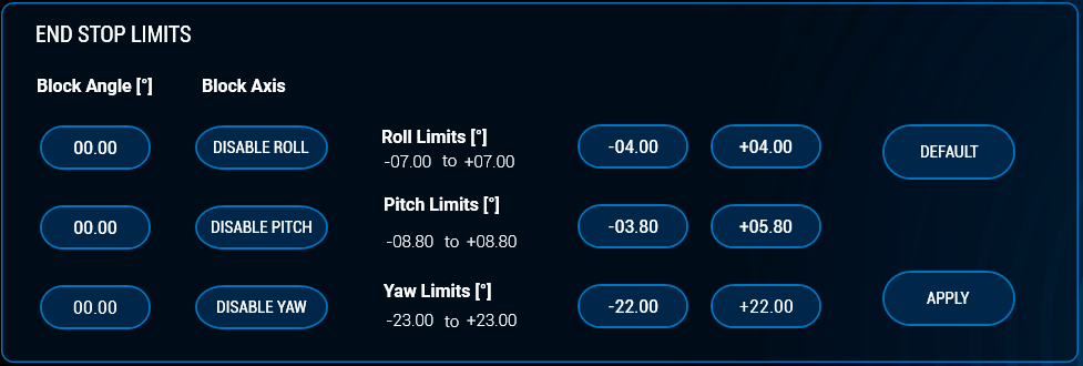
- The End Stop Limits settings allows customers to limit the physical movement range of the Mount in all three space axes. If the End Stop Limits have been applied, the Mount will only move within the specified angle ranges.
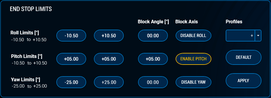
- The End Stop Limits and the Block Axis function are now linked together. The block axis function allows users to block the movement of one or multiple axes.
- Furthermore, an axis blocking now takes place automatically if the absolute difference of the entered end stop values is <± 2°.
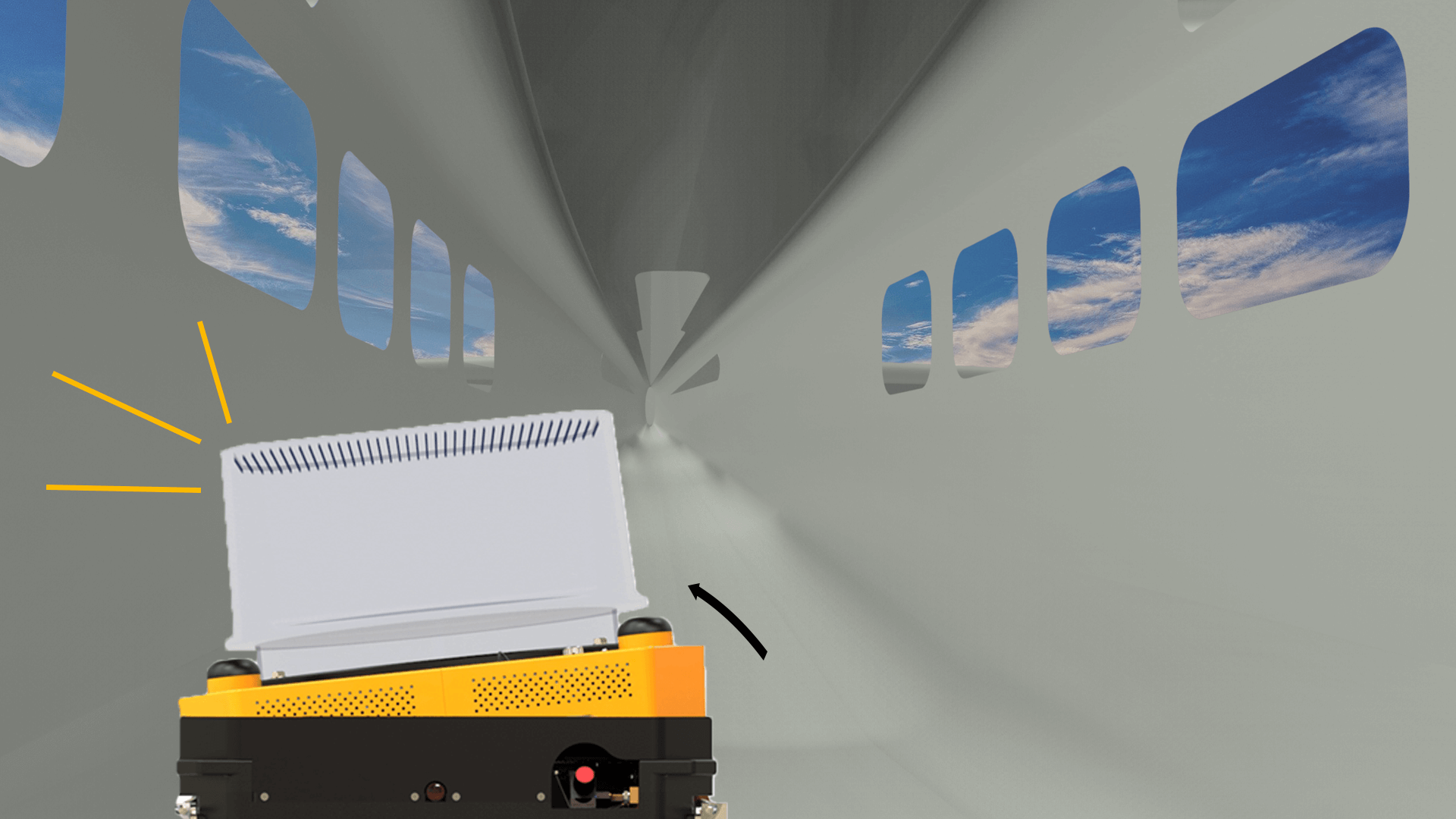
- Limited installation space in the aircraft may result in the sensor system hitting an obstacle such as a board wall during the initialization phase when the Mount is pumping up. The function Pump Direction allows customers to select the side on which the GSM 4000 pumps to working height during the initialization phase. Without feature activation, the Mount pumps up via roll positive by default.
- The Pump Direction function is now linked to the End Stop Limits. This means, if a change of the Pump Direction is necessary due to the restriction of roll and pitch, a possible Pump Direction will be set automatically.
- A novelty of the Collision Avoidance feature is the adjustment of the Mount’s working height. The Mount now automatically adjusts its working height when all four values in roll and pitch have been reduced. In this way, the Mount and the sensor system are protected against a collision with an obstacle also in a non-powered state. The Collision Avoidance feature thus offers the greatest possible safety to avoid damage to the sensor due to restricted installation conditions.
When do I need it?
If the Mount and the sensor have to be installed close to the board wall inside the aircraft or if the hatch in the fuselage is narrow, the sensor system may collide with an obstacle. This may happen during the initialization phase of the Mount or while it is using its full angular range during stabilization. In the past, customers needed several individual software features (End Stop Limits, RTP off and Pump Direction) to avoid collision. This problem is now solved with only one combined Software Feature.
End Stop Limits incl. Block Axis
Refers to: Operating mode (stab/man)
What is it?
Without the End Stop Limits feature, the Mount stabilizes during operation in all axes within its maximum angular range. By activating the Feature “End Stop Limits” the physicial movement range of the Mount can be limited in all axes the Mount provides stabilization for. In the Features 1 screen of your SOMAG Mount Control App you can enter the End Stop Limit values for each axis you want to limit. If the End Stop Limits have been applied, the Mount will only move within the specified angle ranges. The new app version (5.1.0) now allows users to save their End Stop Limits settings as a profile with self-selected names. A maximum of 10 profiles can be created. This makes it easy to switch back and forth between the preferred settings and profiles without having to re-enter the values into the app each time.
Furthermore, the Feature allows you to block the movement of one or multiple axes. Several axes can be switched off simultaneously. Each axis can be reactivated at any time. It is also possible to block an axis at a certain angle.
When do I need it?
This software feature is particularly interesting for customers who need the movement range limitation for use cases other than collision avoidance. If the hatch is too small and the sensor is located too close to the fuselage of the aircraft, this can lead to vignetting problems and thus to dark image corners. To solve this problem and to avoid any back scatter from the aircraft window it is helpful to limit the sensor’s range of movement by activating the feature End Stop Limits.
If your hatch hardly offers enough space for your Mount to stabilize in all three axes and therefore motion compensation in roll and pitch wouldn’t be possible, you can leverage Block Axis to switch off these two axes. So your Mount can at least compensate the drift motions if the hatch offers enough space.
The feature only refers to the stabilisation mode, not to the initialisation phase of the Mount. If you want to use this feature due to space limitations, you should opt for the Feature “Collision Avoidance”.
Leveling Offset
Refers to: Operating mode (stab/man)
What is it?
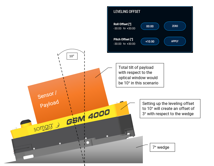
The regular leveling horizon during stabilization is 0 degrees. The Leveling Offset feature allows you to set up a different leveling horizon for roll and/or pitch during stabilization. When the Feature Leveling Offset is active, the Mount stabilizes around the newly selected leveling horizon.
When do I need it?
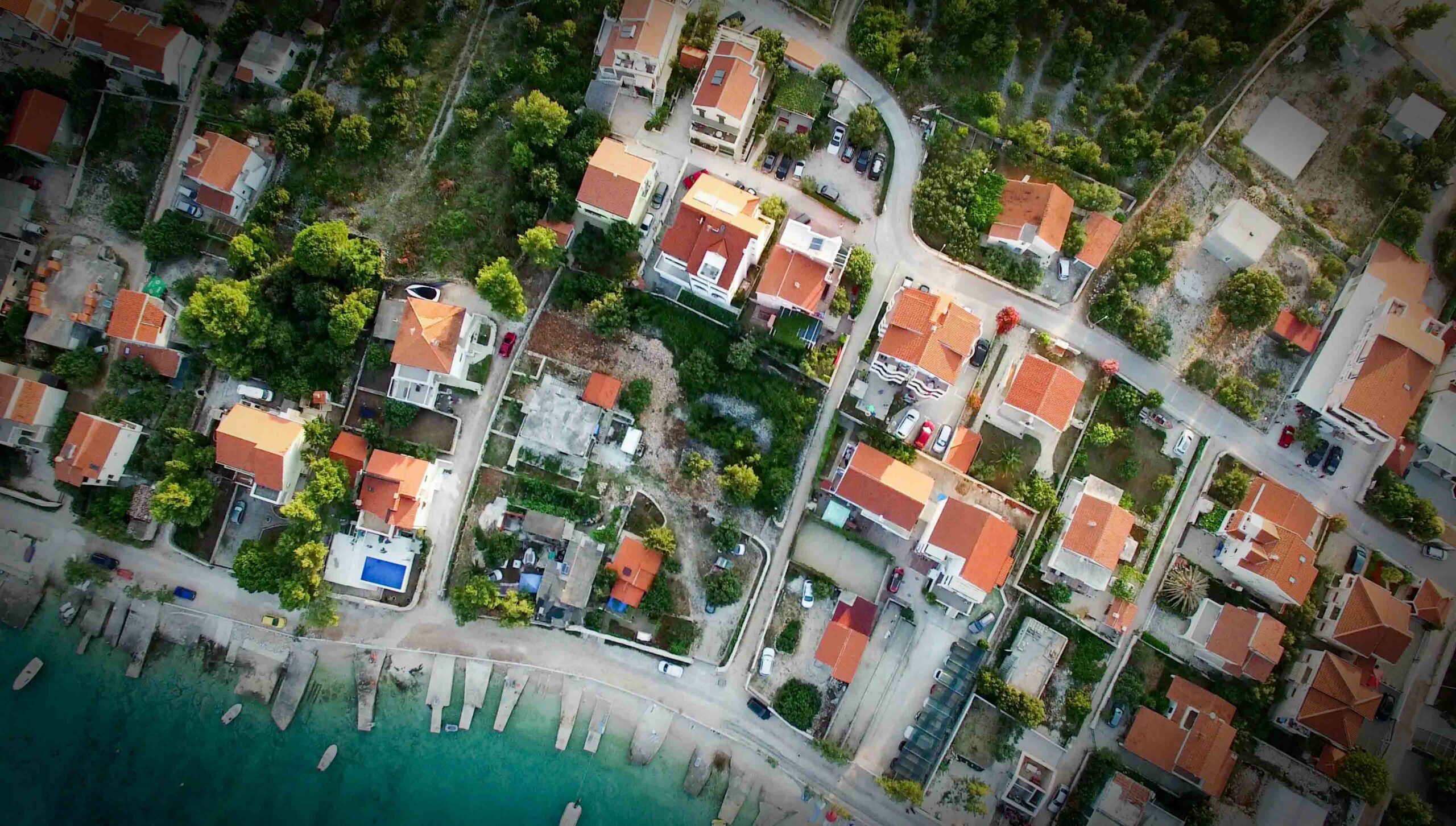
The Feature is useful for setting a direction other than nadir. This could be helpful in various situations. An example: If you collect airborne lidar data over wet terrain, you might have to deal with bright lidar reflections caused by nadir measurements. You can solve the problem by making a minimal change of the leveling horizon with the Leveling Offset Feature and by tilting the scanner and thus the laser slightly. The Leveling Offset feature offers an advantage not only for laser scanners. Single medium format cameras also benefit from it. If you want to stabilize a single medium format camera with our CSM 40, you can take orthophotos with it by default. If you would like to take additional oblique images with this camera, just use our Software Feature and set your offset value accordingly.
Status / Analysis
Refers to: Operating mode (stab/man)
What is it?
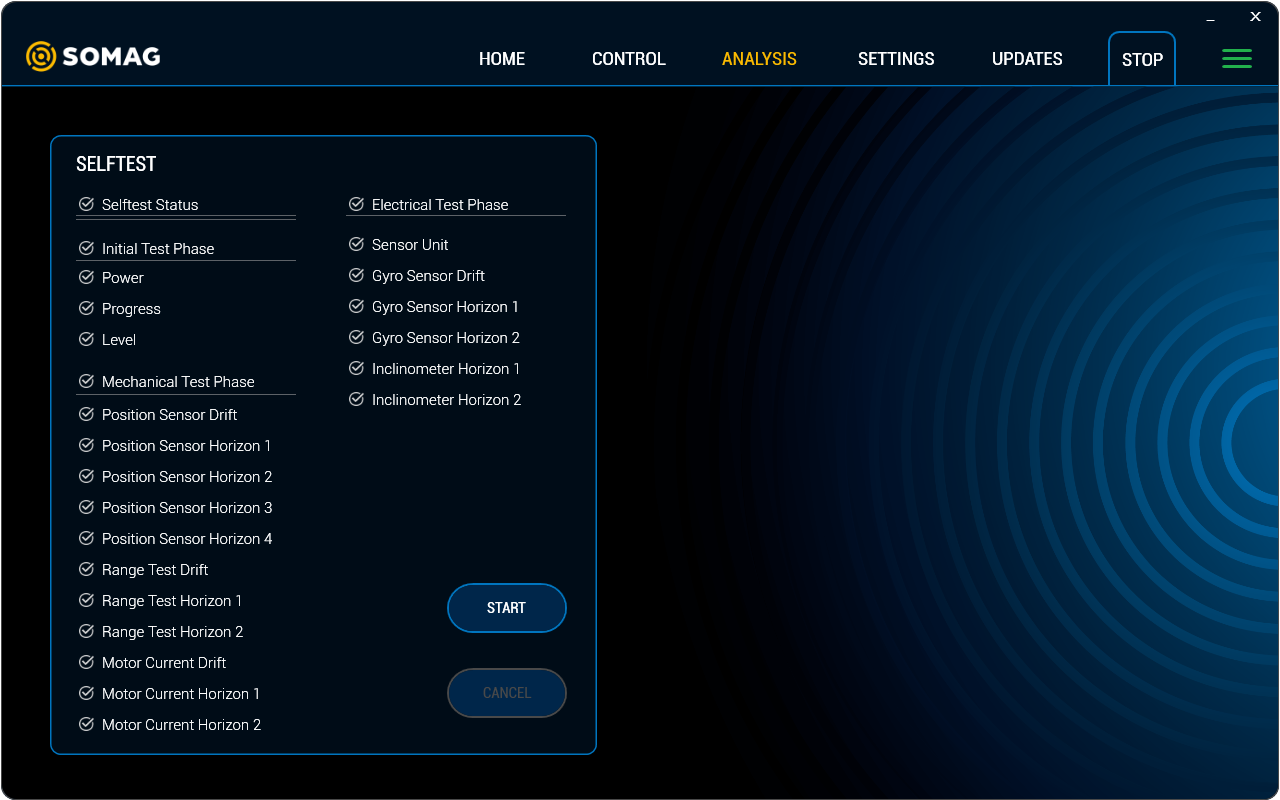
When this Software Feature is activated, various logging and analysis functions are enabled in the SOMAG Mount Control App. When the Feature is activated, four tabs with different information are available: “Visualization”, “Status”, “Diagnosis” and “Variables”. They show, among other things:
- Real-time display of the Mount angles
- Monitoring of Mount variables, such as temperature and working height
- Diagnosis of the Mount in case of malfunction
When do I need it?
This feature is especially helpful for troubleshooting and a fast support provided by SOMAG AG Jena. For troubleshooting the self-test is an important tool. The self-test can be found under the diagnose tab. The Selftest executes a routine for the Mount, which checks all sensors, mechanics and electronics and stores the results in a text file. SOMAG AG Jena can evaluate this text file for troubleshooting purposes. The Selftest is semi-optional, which means that the Selftest can be performed without an activation of the Feature Status/Analysis, but the visualization and thus the results of the Selftest are not visible if the Feature is not activated.
IMU Installation Position on Vehicle Frame
Refers to: Operating mode (stab/man)
What is it?
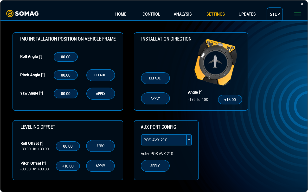
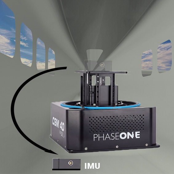
A classical aerial survey system may consist of a Gyro Mount, the camera(s) and GNSS/IMU on top or integrated in the camera. In this case the Mount gets the IMU data via the interface port without the need for a special setting in the Mount Control App. If the Mount is connected to an IMU, which is not installed on the Mount itself this Software Feature must be used to setup the angles of the IMU with reference to the Mount frame.
When do I need it?
If the IMU cannot be installed on top of the Mount due to space limitations or other reasons, this Feature is required. The IMU must then be firmly fixed to the vehicle floor or to another non-moving object. This Feature is particularly useful if, for example, a laser scanner with IMU is already installed in an aircraft and a camera system is to be added. In this case, no second IMU is required, as the Mount can use the data from the existing IMU. In this case, however, the Feature must be installed to ensure that the Mount receives the correct data from the IMU. Please note that the order Yaw-Pitch-Roll must be followed when measuring the angle of the IMU.
Installation Direction
Refers to: Operating mode (stab/man)
What is it?
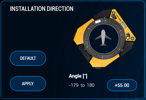
By default our airborne Mounts are installed together with the sensor and IMU in flight direction in the aircraft. If the Mount needs to be installed in a different direction than its preset flight direction, the Software Feature “Installation Direction” becomes necessary. For example, if the Mount has to be installed in an aircraft rotated by 90°, the Mount movement must be adapted to the rotated sensor reference system. For this purpose the angle by which the Mount is rotated must be entered into the SOMAG Mount Control App. The respective field for entering the data can be found under the Features 2 tab.
When do I need it?
This Software Feature is useful if the mounting holes in the aircraft dictate the installation direction or if the Mount would hit an obstacle if installed in flight direction. It is only possible to change the horizontal position of the Mount with this feature. It is important that the installed sensor and the IMU continue to point in flight direction otherwise the Feature will not work properly.
Aux Port
Refers to: Operating mode (stab/man)
What is it?
Our Mounts provide an Aux Port interface. The AUX Port interface allows you to connect an IMU directly with the Mount. The connected IMU can be easily selected and activated in the SOMAG Mount Control App. The following IMUs are selectable by default: POS AVX 210, NovAtel, SBG Spatial FOG.
When do I need it?
This feature is useful if there is no FMS in the aircraft. Then the IMU data can be read directly into the Mount. In maritime applications where a FMS is not used, such as on buoys or ships, the Feature is profitable, as external IMU data improves the residual deviation performance of the Mounts for long term applications.
Frequently Asked Questions
Do I have to buy each Software Feature separately or will all Features be activated after a one-time payment?
Our optional Software Features allow you to customize your Gyro Mount to your individual operating conditions and environmental requirements. It is important to us that you only pay for the Features you really need. We therefore offer each Feature individually for purchase. If you need more than one Feature, we will be happy to offer you an attractive software package.
How can I buy the Software Features?
You can order one or more Feature(s) along with your new Mount. You already own one or more Mounts and want to order Sofware Features later? No problem! Each Feature can be ordered separately at any time! For pricing information, please contact our sales department.
I purchased a Software Feature, how long do I have to wait for the Feature to be made available?
If you order one or more Sofware Feature(s) directly with the purchase of a new Gyro Mount, the Features are already activated when your Mount arrives. A later Feature activation for an already delivered Mount is possible within a few hours after ordering. The advantage is that the Mount remains operational for you during this time and you do not have to send the Mount back to us as an activation can be done remotely. You will receive an activation file, which can then be read in and activated in the Mount Control App under Unlock Features in the Updates view.
What do I need for activation?
To activate and control the optional Software Features, you need the SOMAG Mount Control App. We provide you with the App free of charge on a USB stick included in the standard scope of delivery of your Mount. Features that are not activated are grayed out in the App. After activation they will be colored. A list of all optional Software Features can be found in the App under the Updates view in the Feature Activation Overview field. There is a green check mark in front of each activated feature.
Can I borrow a Software Feature or unlock it only for a certain time?
We do not currently offer a loan or temporary use of our Sofware Features. Once a Feature has been activated, it can be used indefinitely with no time limit and no need for reactivation.
I own several mounts and want the same Software Feature for all of them. Do I have to buy this Feature separately for each Mount?
Yes, the Software Feature must be purchased separately for each Mount. The Feature activation is based on the individual serial number of the respective device. Thus, the Feature cannot be transferred from one Mount to another.We require the serial number of all devices on which the Feature is to be activated when ordering. When purchasing a Feature for multiple devices, we offer attractive package prices.

